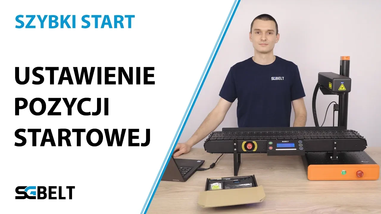
SGBELT leveling – setting the start position in EZCAD
I'll show you how to set up SGBELT conveyor with EZCAD.
Introduction
Setting the starting position of the SGBELT feeder in EZ-CAD is crucial to achieving the best marking results. This process is essential for achieving an even marking result and precise alignment of graphics and text with the feeder slots.
Preparing for setup
The first step is to make sure that both your laser and conveyor are located on a stable surface. Using the spirit level from the kit, check the level setting of the laser head. Adjust the same setting on the surface of the conveyor socket directly under the laser head using the height adjustment on the conveyor legs. The laser head and the surface of the conveyor must be parallel to each other. Loosening the screws that hold the conveyor legs allows the conveyor to be tilted in any direction, allowing it to be aligned with the laser head. Once set correctly, tighten the screws that secure the legs to the conveyor.
Setting the starting position of the feeder slot
Before setting the conveyor position, it is necessary to set the height of the head to the surface of the socket of an already levelled conveyor. With EM-Smart lasers, uncheck the graphics in EZCAD and click F1 on the keyboard (Red) (Beam) to display the second red dot of the focal length lens. Adjust the height of the head so that the two dots merge into one on the surface of the socket.
If you are using a device with autofocus, perform an automatic height measurement.
We will start setting the starting position of the socket by starting the marking machine and the EZCAD program. The setup process will depend on the width of the socket installed in the conveyor:
- For the W15 and W30 sockets, create a 29 x 135 mm rectangle in the program.
- For the W60 socket, create a rectangle measuring 59 x 135 mm.
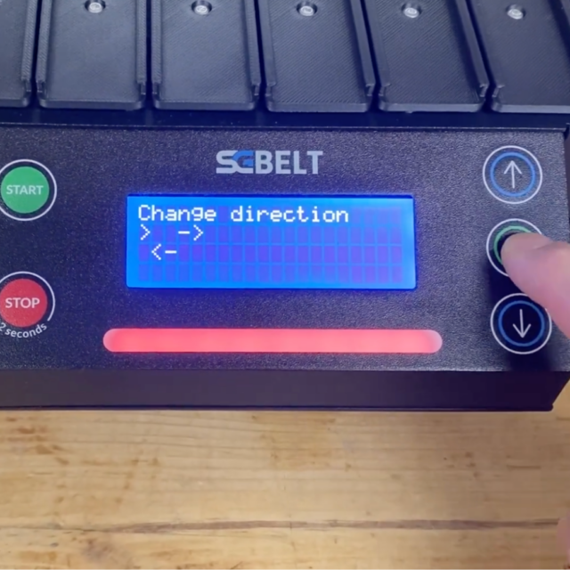
Center the created rectangle on the work field in the program. If you use a smaller lens that does not allow you to display such a dimension, replace 135 mm value with the maximum that you can display. With the conveyor under the marker head, turn the conveyor. In the conveyor menu, go to Settings -> Auto Center and click OK. The conveyor will automatically position itself in the center, relative to the built-in socket sensor. Display the position of the created rectangle by selecting it in EZCAD and clicking F1 (Red) (Beam). The rectangle displayed by the machine is the marking surface of your laser in a single socket. Move the entire conveyor so that the conveyor socket fits the displayed rectangle, also making sure that it is not tilted relative to the preview. If the preview does not cover the entire conveyor plate, be sure to position it so it covers the area of the item to be marked. In the place where you placed the conveyor, make sure to tighten the screws mounting the leg attachment to the marker device plate. Turn the preview off and uncheck the created rectangle.
You might also be interested in this...


