How to Design and Make a Replaceable Plate for the QuickSlide Socket
In this video, I'll show you how to design a cutout for a QuickSlide replacement slot plate for a carabiner. Today, I'll be making the plates themselves using a CO₂ laser from 3mm thick HDF material. I downloaded a previously prepared and verified template, tailored to the slot dimensions in my SGBELT feeder.
If you don’t know which size of the removable plate to choose, below you will find a link to download and test the test file.
Set of templates for interchangeable plates of the W30 socket
Set of templates for interchangeable plates of the W60 socket
Download the socket plate templates by clicking on the link to the article: How to Fit a Laser Cutting File to a Quick Slide Slot
In most cases, the cutout in the plate is simple – its main purpose is to ensure a stable positioning of the item in the feeder slot. However, in this example, I’ll also show how to incorporate a ridge in the carabiner so that the keychain sits flat on the plate.
I’ll start the project by creating a rectangle with the outer dimensions of the carabiner. Then, I’ll copy the elements from the template – the outer edge and the hole for the slot sensor – and center them relative to the center of the plate. I’ll round the bottom edge, and separately add a smaller circle at the top that replicates the shape of the carabiner. After merging the elements, I’ll design cutouts and roundings that will facilitate subsequent removal of the part after laser cutting.
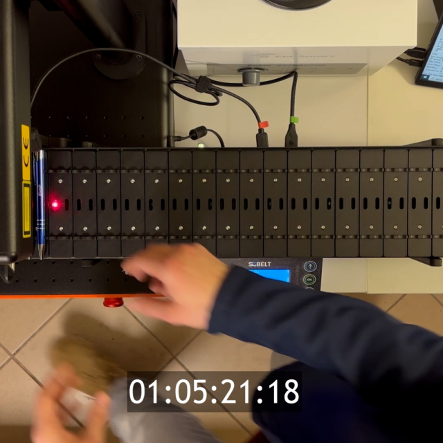
Because the element needs to be positioned relative to the baseline, the plate will consist of two parts that need to be glued together. The first part serves as a frame, and the second as a precise cutout for the carabiner. I cut both parts with the laser, but only score one to mark the gluing point. After a test cut, I check the fit of the item. It turned out that the cutout required minimal adjustments – I increased the length by 0.5 mm and moved the design down 15 mm to allow the snap hook to obscure the slot sensor’s laser beam. After retesting, the fit was perfect: the snap hook lays flat and stable, and the sensor works properly.
Next, I made a full set of 25 plates for the W60 slots, glued them together with cyanoacrylate glue, and prepared the feeder for automatic marking. I imported the logo into EZ-CAD, adjusted its position relative to the snap hook, and set the marking parameters.
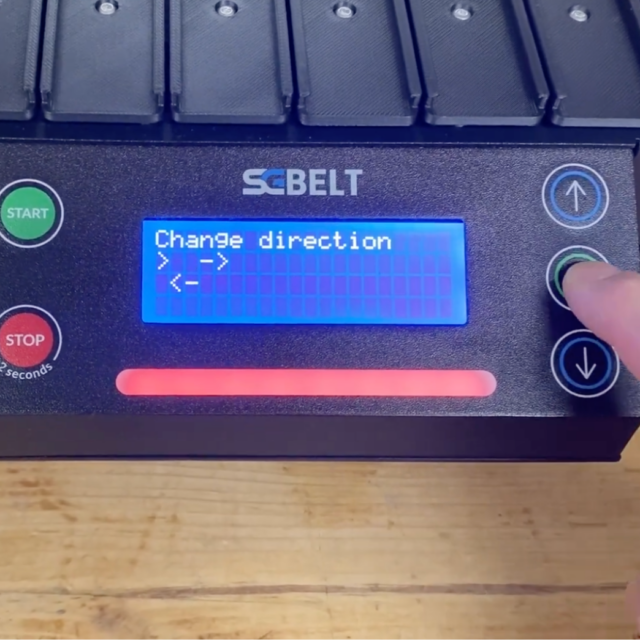
The first marking went perfectly, so I entered the marking time into the feeder controller and launched the full automatic process. Finally, I invite you to watch the next video, which shows all the available slot types for the SGBelt feeder.

You might also be interested in this...